Part 6 - Building the ROV
It was January 2021, and almost four months since we had started working on the case. There was still 5-6 months to go before we could start searching. We needed a way to shoot underwater video to be able to crack the case.
The solution was to use an ROV, Remote Operated Vehicle capable of diving deep and sending video to the surface. Commercial solutions were outrageously priced, so I thought how hard could it be to construct my own.
I got inspired by many designs but the homebuilt ROVs and especially the forum were my main sources of information. I read most of the project threads on the Homebuilt ROVs forum and I came to the conclusion that it couldn’t be that hard to build one yourself. As usual, ignorance is a bliss.
Checking others’ projects I made notes about what I liked and didn’t like about them. Slowly plan started to take shape. The first decision was to go all digital. I knew software better than the analog world, so I would rather be fighting with bits and software than with analog components.
The Dry Hull
ROVs usually have two hulls: a dry hull and a wet hull. The dry hull to contain the electronics and all the other stuff that can’t withstand the water and pressure. The wet hull to protect and provide the frame for the attachments such as cameras, lights, pontoons, and weights.
I remembered that in the early 2000’s, some of the divers built their own diving canister lights. Back then people shared a lot of the information how to build the lights on their websites but by now most of the pages were gone. After grueling Google sessions I found some of the information using the Wayback machine.
The canister lights had a container for the battery, which was usually attached to the diver’s waist. They also had a light head which was attached to the diver’s hand.
Maybe I could reuse this design? The battery container could work as the ROV dry hull, ie. the container for the electronics. I could use the light head design as a case for both, the lights and cameras. I just needed to build multiple cases as I planned on having several lights and cameras.
The parts were not available in the stores, so they had to be custom made. In order to have them made, one needs detailed plans. There were no ready made plans, which meant more learning for me.
The go-to software for creating the plans was Audtodesk Fusion 360. After installing the free version of it and spending a few weeks learning 3d modeling, I was able to recreate the original plans. A week or two later I had modified the plans to include the changes I wanted.
The next hurdle was to find manufacturers. I requested quotes from several shops in China, Europe and Finland. There was a lot of back and forthing, but finally, thanks to Xometry and some personal contacts, I found the manufacturers. The aluminum camera/light cases were CNC’d in Poland and the PE plastic dry hull was constructed in Oulu, Finland.
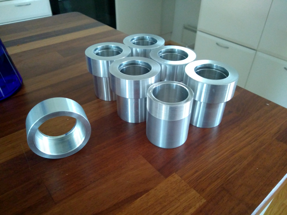 The ROV camera and light cases came from a CNC shop in Poland.
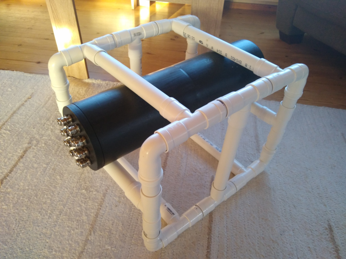 The dry hull (ie. the electronics container) first fitted to the wet hull (ie. the frame).
The Other Parts
The wet hull was made out of a PE sewer pipe. The cameras and lights would be attached to the wet hull. The attachments for the light/camera cases were sourced from Germany. Originally they were meant for musicians, to attach drums to poles but they were perfect for using in the ROV too.
The engines were difficult. The sealed engines for ROVs were made by BlueROV but the price was insane. Lots of googling resulted in a perfect solution: regular drone engines but the ball bearings are replaced with bronze bushings.
Most of the designs in the homebuilt ROVs forum used a battery inside the ROV as the power source. As I had extra Li-Po batteries from the RC-boat, that was a natural solution.
Then there was the matter of networking and tether. The serial connection was not fast enough so a proper network would be needed. Ethernet-over-power adapters, which provided 100mbit/s speed, came in handy. There was a site providing a guide on how to do it with TP-link modems.
For the tether, the standard solution was to push a thin cable inside a rope. The only problem was to find a rope that was long enough. It turned out that even the big, well-known brands, who provided continuous 100 meter ropes, were not that good. In the end, I could only find a 50m rope whose quality was good enough. The first cable I used proved to be too thin. Later, I had to replace the cable with a thicker one, as the connection kept breaking. After changing it, the network proved to be reliable.
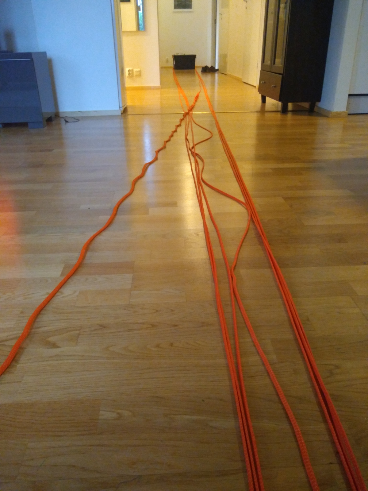 The tether in the works.
The ROV would be controlled by a regular PC gamepad.
The Software
After the hardware was designed and I was waiting for its construction to be finished, it was time to take a look at the software. For the RC-boat, I used Ardupilot, but the ROV variant didn’t seem mature enough.
For the ROVs it was customary to use two computers: one to actually drive the thing, and a companion computer to handle the video and other stuff.
I couldn’t find any proper software to use, except MokiROV. I had originally planned to fork it, but in the end it would have been more work, so I decided to build my own. The ROV ended up having Arduino Mega for driving the engines, reading the sensors, operating the lights and Raspberry Pi 4 to take the instructions from above, and sending the camera feed to the surface.
So, one day I found myself writing C++ code for the Arduino. It required some jogging of the memory, as the previous time I’d done it was 20 years before. The Raspberry Pi portion and the surface computer’s browser were done using node.js/typescript, as I had more recent experience of them.
Constructing the devices was starting to take its toll at this point. I had my regular job and normally after the workday, when I closed my work laptop, I immediately started working on the construction project. I worked on it until 22:00 - 02:00. I dedicated all my weekends wholly to build the thing. The study was so crammed it felt out of control. It started to feel that I had severely underestimated the amount of work required.
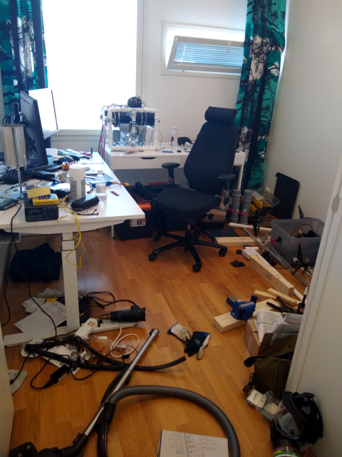 The mess was getting out of hand.
To Try and Err
While assembling the ROV, I noticed that it would have been much more sensible to plan for the o-ring sizes at the design time. I was a regular customer in a local o-ring shop for long stretches of time on Friday afternoons, as it was trial and error process to find the correct sizes.
Eventually all things found their place and the ROV was assembled. It was time for field trials. The ROV leaked during its first three dives. On the fourth attempt everything fit perfectly and the o-rings were correctly sized. No more leaks.
Now all that was left to do was the endless tuning. It was especially difficult balancing the ROV, as even the smallest change in weight caused it either to sink or float. Also the balance of the driving system was difficult to get spot on.
By late June 2021 the ROV was almost finished. By Midsummerfest it had successfully completed its maiden voyage and sent its first video to the surface.
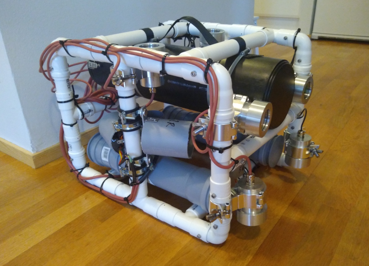 Almost ready to go. Missing the pontoons from the top and adjustable weights from the bottom.
There are 6 cables for the engines, 3 for the cameras, 3 for the lights, 1 for the network, and 1 for the sensors.
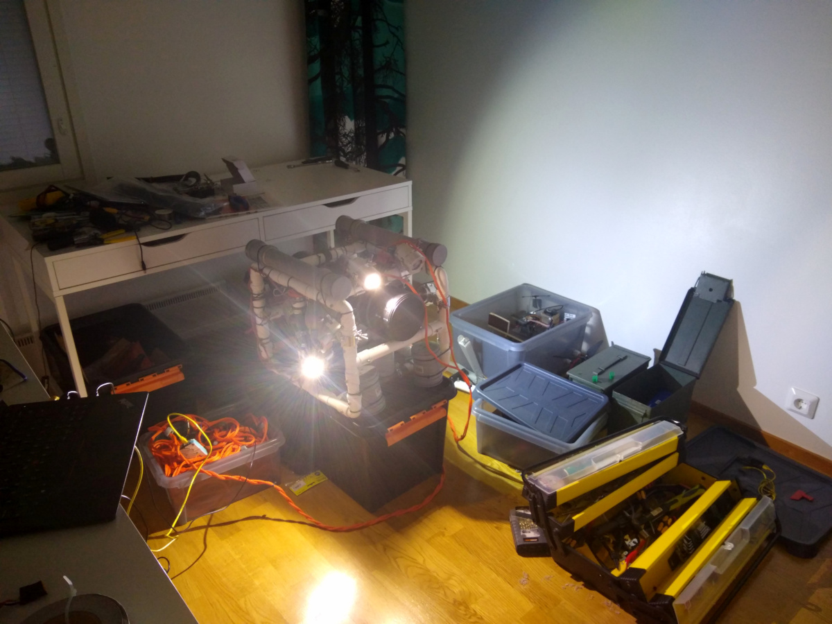 The finished ROV in the study.
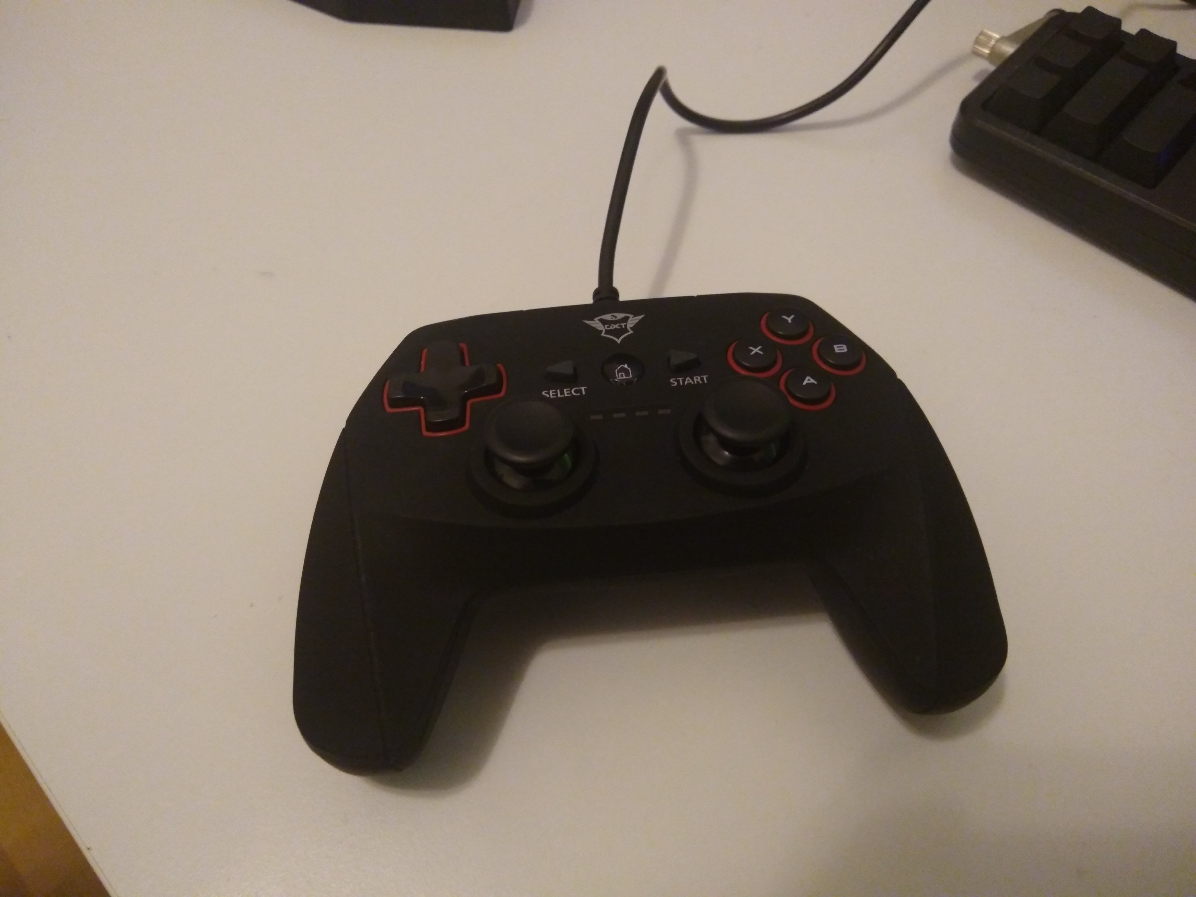 The first controller used. This model didn’t have a long enough range on the analog sticks, which made moving the ROV jerky.